Figure 1: Ropemaker's Bench.
| Home | Equipment | Ropemaking |
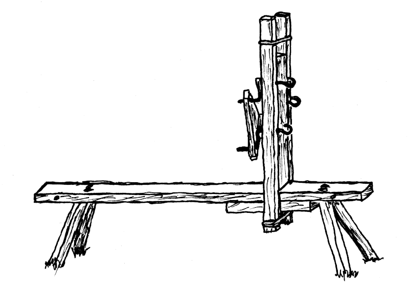
Figure 1: Ropemaker's Bench.
First off, this is not a replica of any known pre-Revolutionary ropemaker's tool. You won't find a picture of it in Diderot & d'Alembert.[252] I designed it. But there isn't anything about it that couldn't have existed in the late 1700s. All the material, and all the techniques used in building it are period correct.
The part that does the twisting, the "jack", had to be stable. Most ropemaking jacks are either firmly anchored into the ground, on a heavy base, or clamped onto something that isn't going to move. I didn't want to dig a posthole every time I set up, and didn't want to lug sandbags around. And I couldn't count on always having a convenient something to clamp to.
So the base is modeled after a woodworker's shaving horse, or a cobbler's bench. The person turning the Cranks is seated on the long part of the bench, which keeps the whole thing from tipping over, and any excessive force pulling on the hooks causes the front legs to dig in.
It had to be usable by everybody from seven year old children to grownups, without a lot of adjustment. Preferably none at all.
It had to be simple to operate. I can teach a six year old how to turn the Cranks in one minute. Adults sometimes take longer.
It had to be safe.
The original was made from Home Depot white pine, because that's what I had, and I didn't know if the design was going to work. (You can see the painfully pale pine 2014 version at Caitlin Garvey's site here.) After several years, the holes that the Cranks turned in were starting to get sloppy. At that time, I had access to a saw mill and some oak, so I replaced the three uprights parts, Figure 3, B and C, with oak. The rest is still working fine in pine, some seven years later. (Bench as of 2020 can be seen here.)
The Cranks I had made had hooks on the end. I chose hooks over pinned Cranks because they are easier to loop strings over, especially when there is a lot of twist already on the strings.
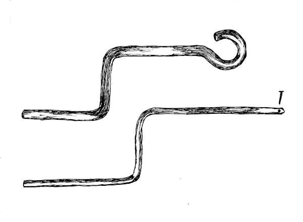
Figure 2: Two Types of Crank.
Since you can't push the hooks though a drilled hole, the crank bearing holes had to split in two pieces. That meant the board the cranks pivoted in would have to come apart every time I packed up after a show. These pieces had to stay put, once the pieces are together, so the holes didn't get out of alignment and pinch the cranks. And everything had to clamp together somehow so it didn't fall apart while making rope.
Making all three cranks turn at the same time presented several options.
All dimensions are nominal. I wasn't following any plans, and there's no reason you should either. The lumber you use is whatever your wood pile or wallet allows. But sand off any sawmill ink stamps, and soften the corners so it doesn't look too much like modern dimensional lumber. A little dirt, a few stains, a couple of dings, this all adds character. Makes it look like a home made bench, which is exactly what it is, and what it would have been in the 1700s.
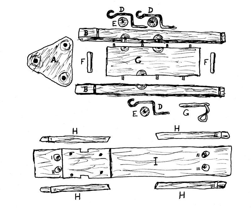
Referring to Figure 3:
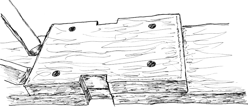
Figure 4: The "Belly".
The two notches for the Side Uprights (B) are cut in the middle of the belly's length, and are narrow enough that the Side Uprights will be snug. The notches are only half as deep as the uprights, for no particular reason I can remember. This does make the Center Upright (C) a little wider than if the notches were as deep as the Side Uprights.
Two holes are drilled crosswise across the main seat board, a few inches from each end. A piece of oak doweling is glued into each of the holes to keep the seat board from splitting, if it had a mind to. I don't know if this was necessary, but the Seat hasn't split, so it hasn't hurt.
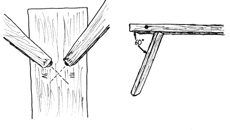
Figure 5: The Leg Holes.
The leg holes are drilled 8" from the ends. The holes should be just a shade smaller than the smallest dimension of your Legs. A worm's eye view shows the legs are splayed 45 degrees, and a side view shows how they are 60 degrees from the bottom plane of the Seat.
I've cut a slot down the middle of the top ends of each leg, parallel to the ends of the Seat. This provides a little compression space, and keeps the legs from binding on wet days. I was thinking of wedging the legs in place when I first built the bench, but being able to dismantle it has become more important than permanence.
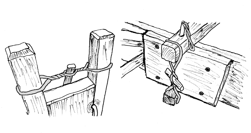
Figure 6: Top and Bottom Tightening Bands.
The Center Upright (C) is trimmed to be as wide as the space between the notches in the Seat board. The notches can be adjusted later if the Center Upright ends up a little too narrow.
Stand the Center Upright on the Seat between the two notches, and put one of the Side Uprights in the notch, next to the Center upright. Slide the Side Upright so the bottom tightening band groove clears the bottom of the belly, and you have enough room to twist the Tourniquet Stick (F). Mark the top of the Seat on the Side Upright, and transfer that dimension to the other Side Upright. It's helpful if you lightly write a "T" on the top edge of each of the three Upright pieces for later reference.
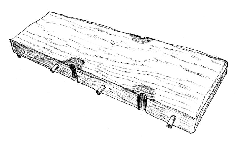
Figure 7: Center Upright.
Pick a spot on the edge of the Center Upright a few inches from the end you've chosen to be the top. This will be the top Crank hole. At 60 degrees from the edge you just marked, mark the spot on the other edge for the second Crank hole. From the second Crank hole, come back 60 degrees to the first edge, and mark the third Crank hole. The holes should form an equilateral triangle. This is important because it means the holes in the Linkage (A) are also an equilateral triangle, and the linkage will fit over the Crank handles with no fuss, no matter how it's oriented.
Clamp the Side Uprights to the Center Upright, making sure your marking lines are lined up, and the Crank hole marks are towards the top. Drill your three Crank holes at the juncture of the Center and Side Uprights. These should be as close to the diameter of your Cranks as possible. They will be tight at first, but will work in soon enough. A little bacon grease or bees wax will help them turn in the beginning.
Now separate the Uprights, and drill dowel holes in the edge of the Center Upright between the Crank holes. The dowel holes should not be is the same position on both sides. That only leads to confusion when setting up. Glue the dowels into the Center Upright, and mark their position on the Side Uprights, making sure your tops are still tops. The dowels are glued into the Center Upright because it is narrower than the Seat, so when you are packing up after a demonstration, (Figure 8, below) the dowels are somewhat protected by the Seat, and less likely to snag or get broken. Drill the dowel hole in the Side Uprights, and check for fit.
Reading that last part over again, it makes more sense to drill and set the dowels first, then drill the Crank holes. That's hindsight.
Drill the Upright Anchor Peg hole through one of the Side Uprights into the belly of the Seat.
To set up:
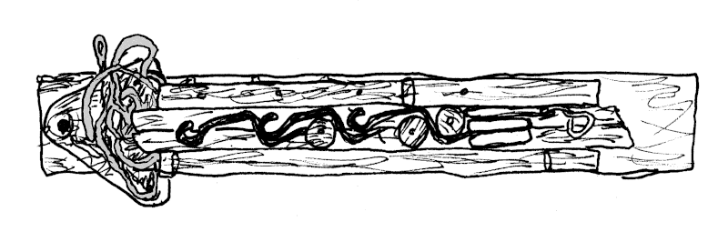
Figure 8: Ropemaker's Bench - Ready to Pack
When broken down, stacked as in Figure 8 above, and wrapped in canvas, the bench becomes a manageable 4 foot long 9" x 6" bundle, weighing just under thirty pounds.
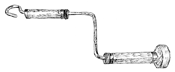
Figure 9: Wire Crank Traveller.
grips are wood, drilled then split, glued back together, and finished off with copper ferrules. The end knob is only an inch and a half diameter.
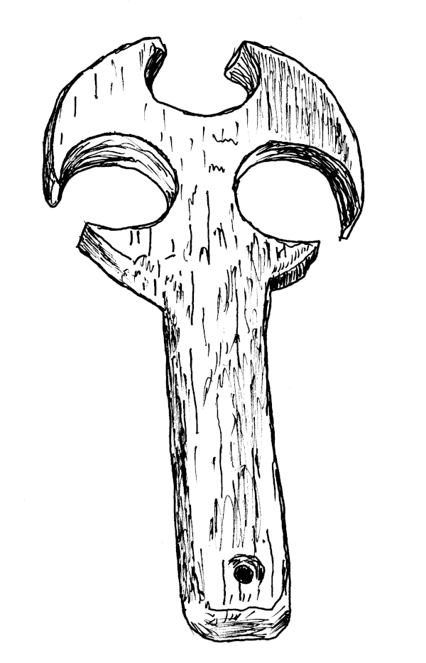
Figure 10: Flat Wooden Top.
Keeps the strands from twisting together too soon. When I was making this sketch, I noticed the hole I'd made at the end of the handle. There should be a cord through there to hang it up. Then I wouldn't have to keep looking for where I put it down last.
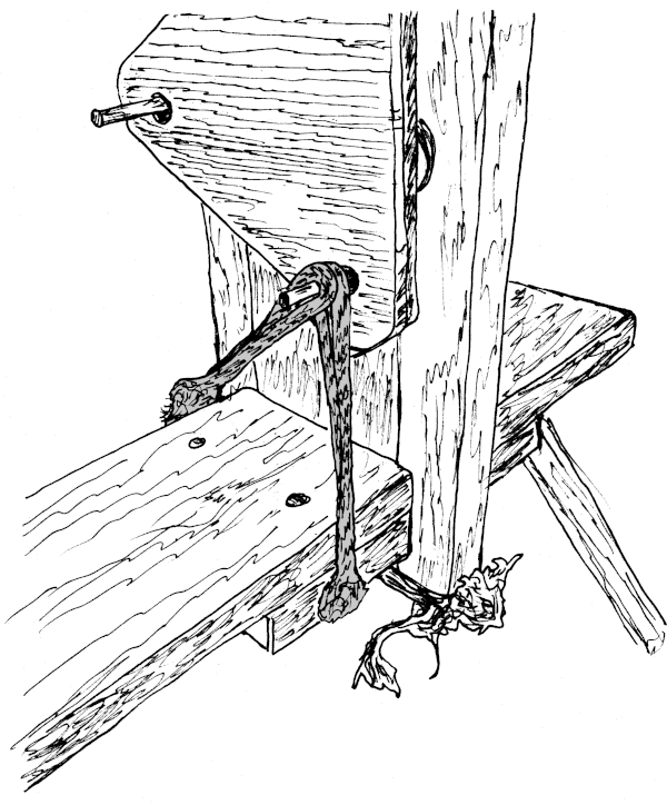
Figure 11: Parking Brake.
This is just a piece of rope with an eye-splice on each end, sized to hook over the bottom Crank handle, loop under the bench belly, then snugly back to the Crank handle. This keeps the bottom hook from twisting, and if the Linkage is in place, all three Cranks are locked.
I should come up with a better name for this thing.
In February 2022, I was giving a demo inside, and the end of the reel axle slipped around on the floor. I drilled two 5/16" holes through the tops of the Side Uprights (B). Now I can mount my reel horizontally, and it doesn't interfere with someone sitting on the bench, turning the Cranks.
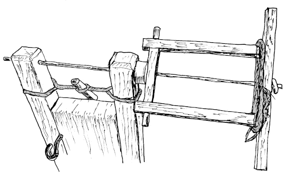
Figure 12: Two Armed Reel Mounted on the Bench.
Now I'm wondering what else I can add to the bench.
| Colophon | Contacts |